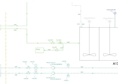
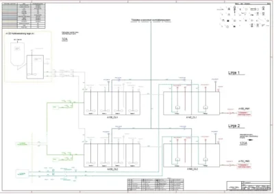
P&I diagrams
P&I diagrams are done by KAMI’s engineering department
KAMI’s engineering department often works for our own customers, so if you need P&I diagrams, we are ready to help. If your task goes beyond mechanical design or calculation to P&I diagrams, we can help you with this – and if your task is purely P&I, we can also help you solve it.
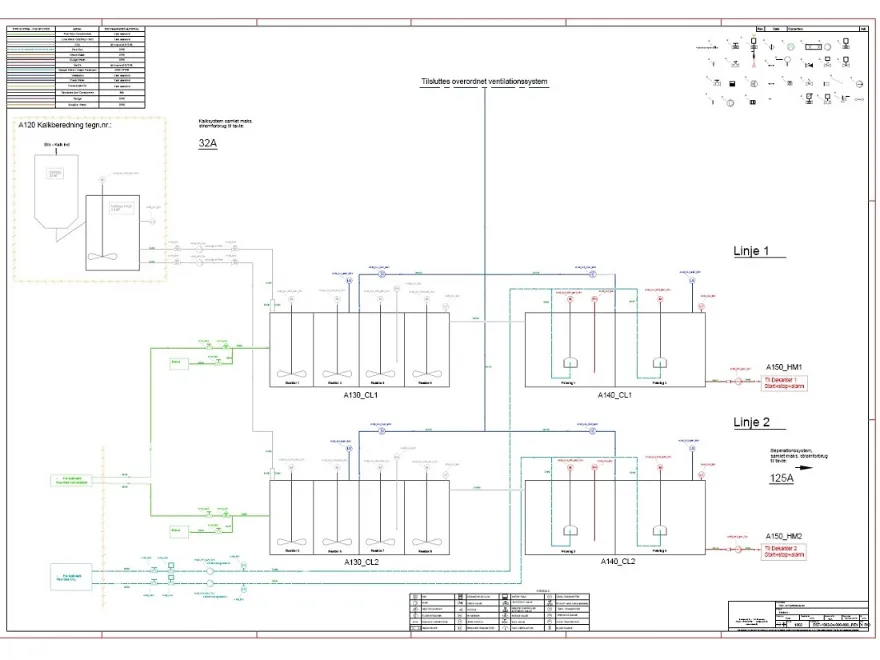
P&I diagrams can be done by you or by us

If you need P&I diagrams, we can do the work locally at your site or we can sit with us. If the task needs to be executed on your equipment/license, we can do it, but we can also perform the task in our own facilities with our own licenses. We adapt to your needs – and start, execute and finish the job where it makes the most sense for you.
P&I diagrams are most often used to provide an overview of process and tank facilities
Process and Instrumentation (P&I) diagrams are used to provide an overview of process and tank facilities. Diagrams are helpful when performing service and maintenance. Based on your requirement specification, we can draw up new P&I diagrams for new facilities or we can update existing documentation, for example when expanding an existing facility. If you have your own standards for symbols, we can work on your layout, or we can use our templates/masters to create a diagram based on common symbols. Depending on the level of detail, we can number and, for example, create instrumentation lists with roof numbers so that service and maintenance can be planned and recorded.
We can create P&I diagrams according to relevant standards
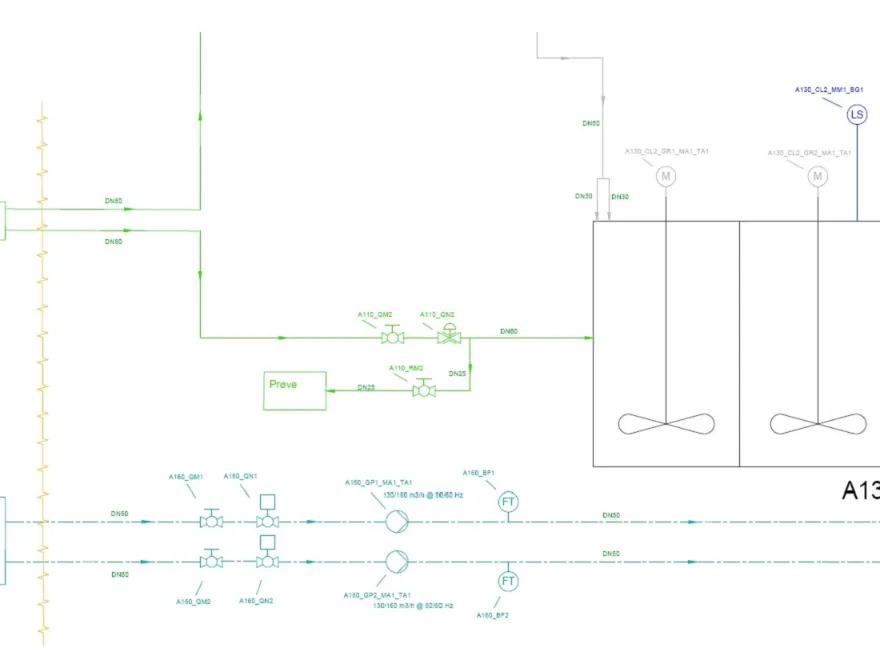
P&I diagrams can be supplied so that the symbols comply with ISO 10628 and ISO 14617. We can also ensure that the roof numbers / decals / labels that connect the diagram with the physical components can be made according to ISO/IEC 81346. If you have your own requirements or standards you want to comply with when creating diagrams, we can of course work according to these. Through a kick-off meeting and an alignment of expectations, we ensure you get the diagrams you want.
We use AutoCAD for P&I diagrams – if you have other requirements, we can accommodate them
Our designers use AutoCAD internally to create diagrams in DWG, DXF and PDF format, but if you have specific requirements for other programs, we can of course accommodate them. The lists we most often extract via AutoCAD can be some of the following, for example:
- Piping lists
- Valve & engine mouldings
- Dashboards
- Flow & function diagrams
- Process diagrams
All lists can be prepared and printed with associated tag numbers for traceability between the components and the diagram in question, and if desired, relevant part numbers and specifications can be included – we adapt to your needs.

We can work with control suppliers to find the best solutions

If you have chosen the management suppliers for your project, we can work with them to ensure that the P&I diagram is designed to suit their specific needs. Through our supplier network, we can also put you in touch with the supplier we think will do the job best. Our designers can handle all communication with each supplier, we are used to interdisciplinary tasks – so we adapt to your needs!
Contact us if you need an engineering job done
KAMI’s engineering department can provide a wide range of engineering services in addition to P&I diagrams. Among other things, we perform 3D construction with derived production basis and working drawings, and we can also perform FEM calculations. In addition to mechanical services, we also offer documentation, such as CE markingand we can prepare visualizations for your next sales prospectus. Does your delivery also include steel production we can take care of that part – so please contact us if you want to talk about your next project or need advice on a specific engineering task!
Contact us to find out what we can do for you
We also offer services like these
Visualization
Design via 3D scanning
